Introduction:
A Hydrostatic slide is non-contact in that the slide is supported by a film of high pressure oil, in the order of 10 Um. It functions by producing a continuous flow of high pressure oil through and out of the bearing. The flow rate being controlled by restrictors. The restrictors allow the slideway to cope with varying loads and maintain a near constant film thickness. Throughout the bearing surface, small pockets or pads are machined to create areas of high pressure fed by these restrictors and from which the oil flows ,to the rest of the bearing surfaces before exiting the bearing. The oil is then collected, filtered, repressurized, and recirculated. [Handbook, pg. 294]
ANANT JAIN
Non-Round Grinding Algorithm
Introduction:
The Grinding of non-circular contours on a cylindrical grinding machine is known as non-round grinding. This is achieved by interpolation in the wheel in-feed (linear) X-Axis and the work-piece (rotation) C-axis
Need:
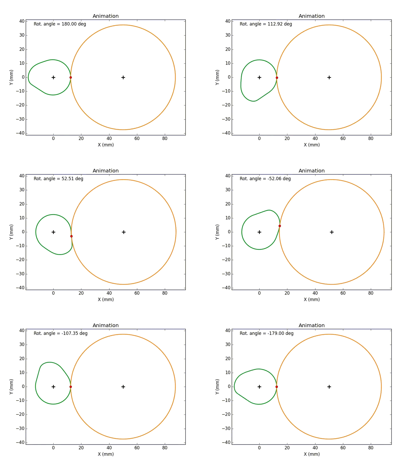
Non-Round grinding requires a software to generate the NC tool-path for synchronizing wheel-head in-feed and retraction with the work-piece rotation. The software used at MGT uses sub-optimal constant work-speed to avoid violating the physical limits (velocity, acceleration, and jerk) of the drive at any segment of the work profile. In Figure-1 It can be easily observed that the wheel-head in-feed experiences high velocities at ramp and nose of the cam but is stationary at the base circle of the cam lobe

Personal Contribution:
Figure 1: An Animation depicting wheel-head movement tracing a cam lobe profile during non-round grinding
I developed a non-linear feed optimization algorithm using gradient-projection technique to compute variable work-speeds at different regions of the component. This ensures the lowest cycle time while adhering to the machine’s kinematic limits.
The Optimization Problem was set up in the following manner:
-
Objective Function: Time taken for one complete rotation of the workpiece
-
Design Variable: Design Variables were the work-speed at each degree of the cam profile
-
Constraints: The constraints were the kinematic limits of the in-feed axis of the grinding machine. The constraints have been noted below as:
-
X-Axis Speed < 0.15 m/s
-
X-Axis acc^n < 4 m/s^2
-
X-Axis Jerk < 35 m/s^3
-

Figure 2: A plot showing constant work RPM (in blue) as well as optimized feed with variable work-speeds (in-green) at different regions of the cam-profile
As it can be seen in figure-2, in case of constant work-speed grinding the kinematic limits of the machine are violated at one portion of the cam-lobe, but the entire lobe is ground at lesser RPM.

Figure 3-A: Velocity, Acceleration, and jerk experienced by X-axis during constant work-rotation at 40 RPM.

Figure 3-B: Velocity, Acceleration, and jerk experienced by X-axis during variable work seeds obtained after feed-optimization
Accomplishments:
-
In Figure-2 it can be observed that in case of optimized feed, the work-speed reduces during the ramp to maintain all kinematic limits, similarly, the work-speeds are higher at the base circle as well as nose region
-
In Figure 3-B it can be observed that all parameters such as velocity, acceleration, and jerk are within the limits specified above
-
The increased work speed lead to a reduction in cycle time by almost 22%
Major Learnings:
-
Linear-Algebra
-
Non-Linear Optimization
-
NURBS and B-spline curves